TIMM'S BMW E31 840i AND E32 ECU REPAIR
M60 V8 ENGINE
SINGLE
CYLINDER FAILURE
HOW THE FAULT SHOWS ITSELF
If you have a single-cylinder failure on the E31 840i or E32 M60 V8 it is not immediately
noticeable, in fact, the problem is often confused with wheel wobble when the
car is in 5th gear. The difference between a single-cylinder failure and wheel
wobble is that when the throttle is lifted the 'wobble' immediately goes away.
The tick-over will be slightly lumpy, but the V8's are quite lumpy anyway. The
power will be down also, but the easiest way to ensure this is the problem is to
remove the plugs.....7 of them will be white and one will be brown:
It is always difficult finding what is to blame when one cylinder out of 8
fizzles out, in this case the fault was initially traced to one cylinder due to
the colour of one of the plugs (hence the title of the original thread), 7 of
them were VERY white, to the extent that I was worried about piston damage, but
one of the plugs was quite brown, and wet. The brown is unburnt oil due to that
cylinder being completely disabled, the white on the other plugs is due to fresh
air that was passed by that cylinder upsetting the O2 sensor and leaning out the
other pots.
I had a good listen to the injectors using a stick pressed to my ear (although a
stethoscope would have been better), the faulty cylinder's injector was not
doing anything. This is what is expected with an ignition failure, if the coil
does not fire neither will the injector.
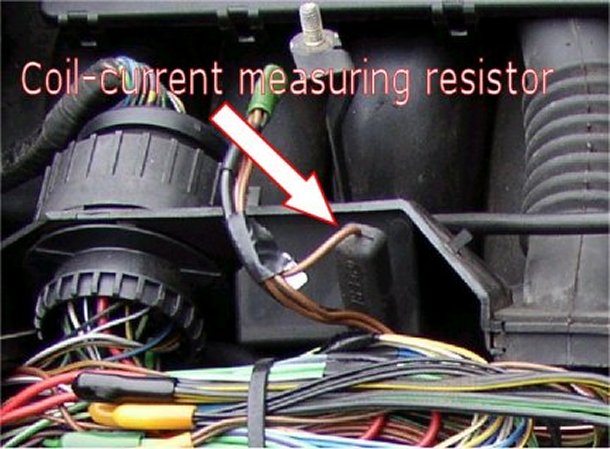
The current going to each coil is measured across a resistor in the wiring boxes
above the cylinder banks, the lack of current in a coil is seen as a failure of
that coil and the injector is disabled to prevent Cat failure and cylinder
wash-down.
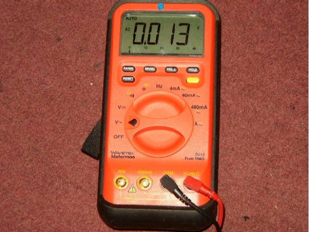
The injector could well have been faulty, but this can be tested with a meter
set to AC volts (digital meter is best). With the wiring cover off, the injector
connector can be probed (but don't push the two contacts together) for each
cylinder. You should expect to see an AC reading of a couple of volts depending
on the filtering within the meter with the motor idling. A missing drive will be
seen as no volts at all.....
The injectors should always have a live feed of the battery voltage (around 14V
with the motor running), the other side is connected to the DME and is pulsed
low. If nothing is happening it is time to check if the coil on the dodgy pot is
firing. Unfortunately, there is no easy way to get to the coil wiring without
pulling the covers off where the wires from the coil join to the wires to the
DME. .....
However, if you own, or can borrow an oscilloscope then it is easy to check the
coil without breaking into the wiring by clipping the probe around the pulse
feed to each coil......
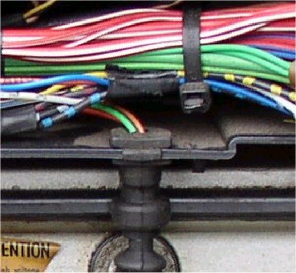
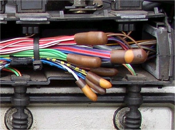
Each coil has a brown wire (negative return) and a green wire (battery voltage).
Each coil has a third wire which is a different colour for each coil. The plan
is to hook the probe around (but not breaking into) these individual wires. A
good drive can be seen as a positive going pulse, short in duration with a long
low period. In reality, the coil is switched ON for most of the time (by pulling
the pulse input to 0V) then switching OFF the coil (and so the pulse input goes
high) to produce the spark. With this capacitive pickup the pulses are very
noticeable, my dead cylinder showed no pulse at all. If this is the same
situation on your car first check that the coil is getting both the battery
voltage and the 0V by disconnecting the coil connector (with the engine OFF) and
then switching the ignition on and checking for those voltages. If all is OK
then it is time to check that the pulse input is electrically connected to the
DME....
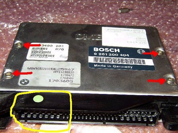
I don't have a picture of the connector that connects to the DME but instead
here is a picture of the DME's connector which will mate with the connector (er..obviously)....
I have circled the contacts that are used for the coil outputs. You should be
able to meter between each coil connector and one of the mating contacts of the
DME connector. If all 8 reach here the wiring is OK (mine was).....
OK....so....we now know that one coil is not firing and that the wiring is OK.
Time to take the DME out and apart. To do this, see the thread in this section
on how to fit a Star Chip (just below this post). Get to the point where you
have access to the EEPROM....
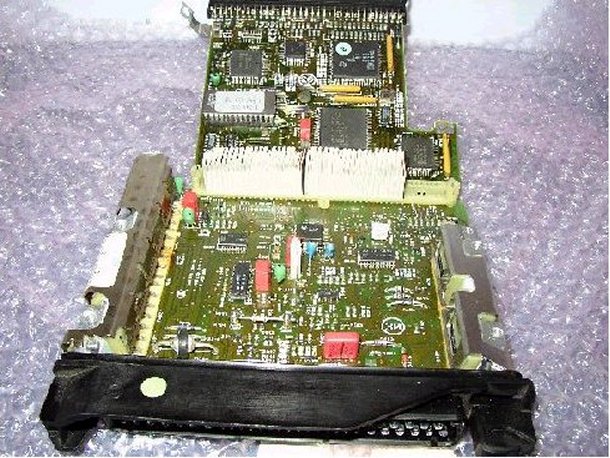
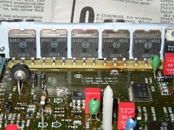
To the left of the last picture the output transistors can be seen under a long
heatsink. There are 8 transistors, one for each coil, plus a couple of other
bits, the regulator and an...um....something else... You now need to get the
heatsink off...even at this stage it is obvious that one of the transistors has
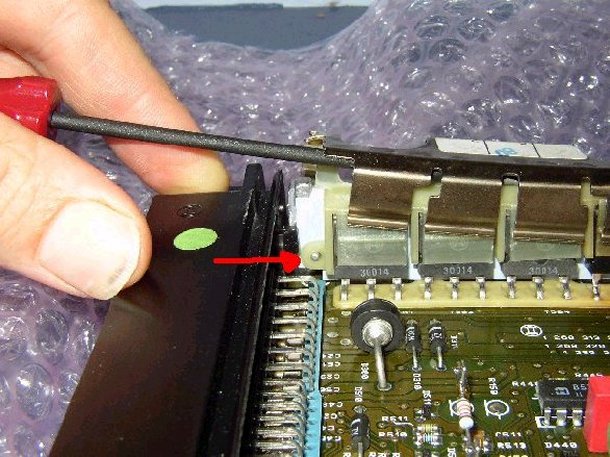
failed due to the burn marks near it.To get the heatsink off lever it upwards
with a screwdriver, don't lever the insulator at the same time because it snaps
the location pin off (ask me how I know)....... Lever each end a bit at a time,
it is quite tight and springy, however, the transistors are quite hardy and do
not mind at all....P.S. the red arrow points to the insulator clip, this will
snap off if you try and lever the insulator up at the same time...
Insulator off.....let's play 'spot the dead transistor'...no prizes....P.S. The
transistor has not changed colour, it's the new one, I took the pictures after
the repair.
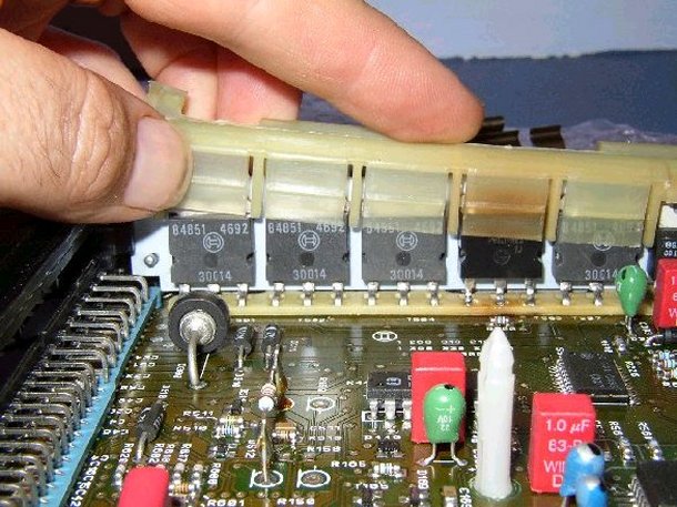
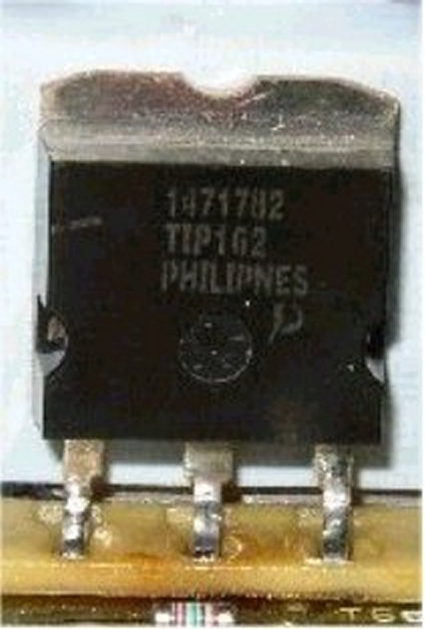
Here's the original transistor fitted. It's got a Bosch number on it but a
replacement is the TIP162 from Farnell for a £4.41 (Order Code 426910)...
http://uk.farnell.com/jsp/home/homepage.jsp
Or for our non-UK readers:
http://www.farnell.com
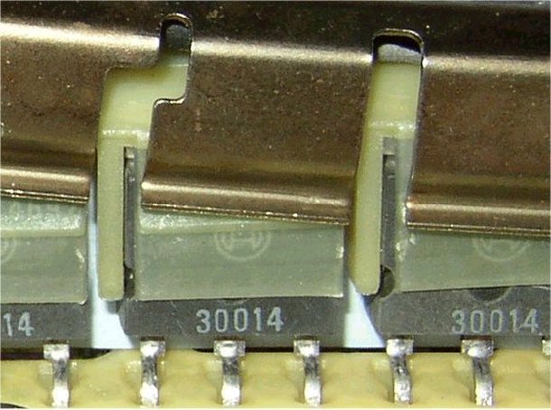
The transistors can be measured using a meter set to 'diode checking' mode where
the leg to leg reading will be different for the faulty transistor compared
against the other ones (base to collector and base to emmiter should show
continuity only with the POSITIVE probe on the base).
It was obvious who the Bad Boy was here due to the scorched insulator.... The
base is on the left-hand-side of each transistor...
Time to get the transistor out. I recommend using a solder-sucker and a
temperature-controlled iron, flow some new solder into the joint to start with,
it makes the solder flow a lot better. As the transistor leg is a good fit in
the hole (and the hole is through plated) it is possible that you will not get
all the solder from between the leg and hole, a little wiggle will soon release
the transistor. The new transistor will need to be prepared as the heatsink will
be longer than required. This needs to be cut half way across the hole and then
filed into this final shape. Bend the legs of the transistor to the same shape
as the old one and place it in the PCB making sure that it stands at the same
height as the others....then solder it in....
P.S. Never cut the heatsink with side-cutters or tin snips as the transistor
will be damaged due to the deformation of the metal...
OK, slip the insulator over the transistors and ensure it is located in the
little dowels as shown before and then press the heatsink over the assembly. It
is quite a tight fit, and still rather springy. Make sure that the heatsink is
properly located over the insulator as shown here with the springy bits on the
transistors and not between....
Right....time to stick it all back together.
Follow the instructions on the Star Chip thread on how to re-assemble and refit
the DME in the car.
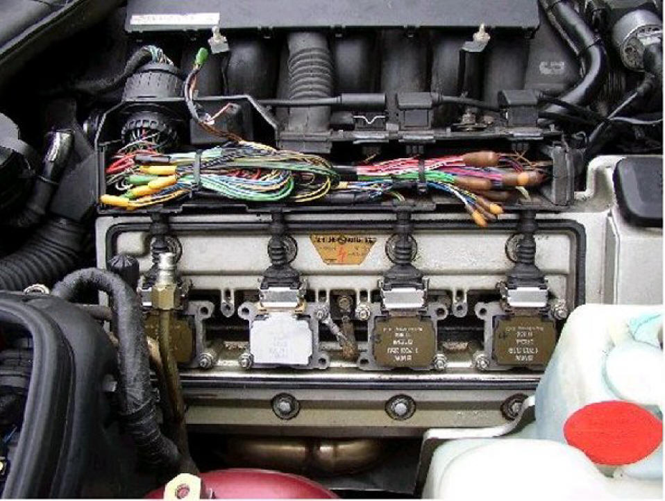
IMPORTANT:The usual cause of a transistor failure is due to a faulty
coil-over-plug unit. Although mine still worked when I moved it to another
cylinder, I decided that for around £30 I would rather be safe than sorry...so I
stuck a new one in.... We can play 'spot the new coil' now if you want...
Do not be surprised to find that when you first fire the car up it will idle
like a Nikasil infested 300K miler. That is quite normal, as we have just done a
miracle 'reset' on the DME.
It will soon sort itself out after a bit of driving......
All done, time for a cup of tea......

![]()
