TIMM'S PERFORMANCE CHIPPING
THE E31
840i, E32
730i AND 740i, AND EARLY E38's WITH THE M60 V8 ENGINE
![]()
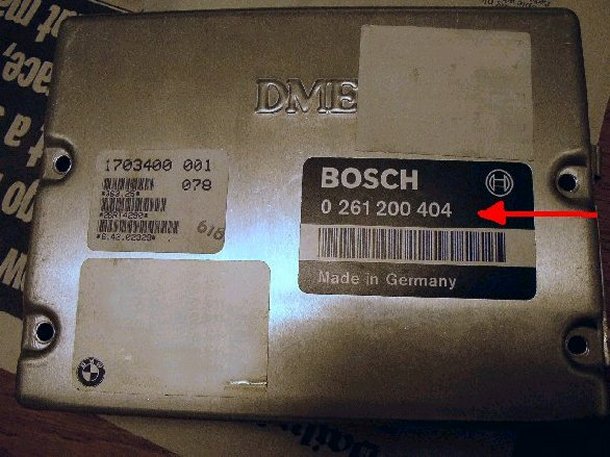
These instructions are suitable for
fitting new software (Chip) in BMW M60 V8's that are controlled by the Motronic 0261 200 404
or 0261 203 484 DME's. Although other DME's are similar there may
be slight differences, some older DME's have a single PCB construction, the DME
we are working on has two PCB's.
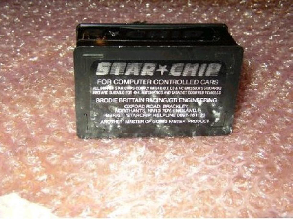
I fitted a BBR StarChip, this was around £150. They can be found here:
http://www.morego.co.uk/bbr-gti/StarChip.php
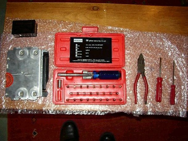
To start with you will need a few tools, a Torx set (although you really only
need two sized bits), a pair of pliers and a couple of flat-bladed screwdrivers.
Find somewhere clean to work, a plain wooden table is suitable as this will
discharge any static, don't try and do this on a plastic table!
Tools:
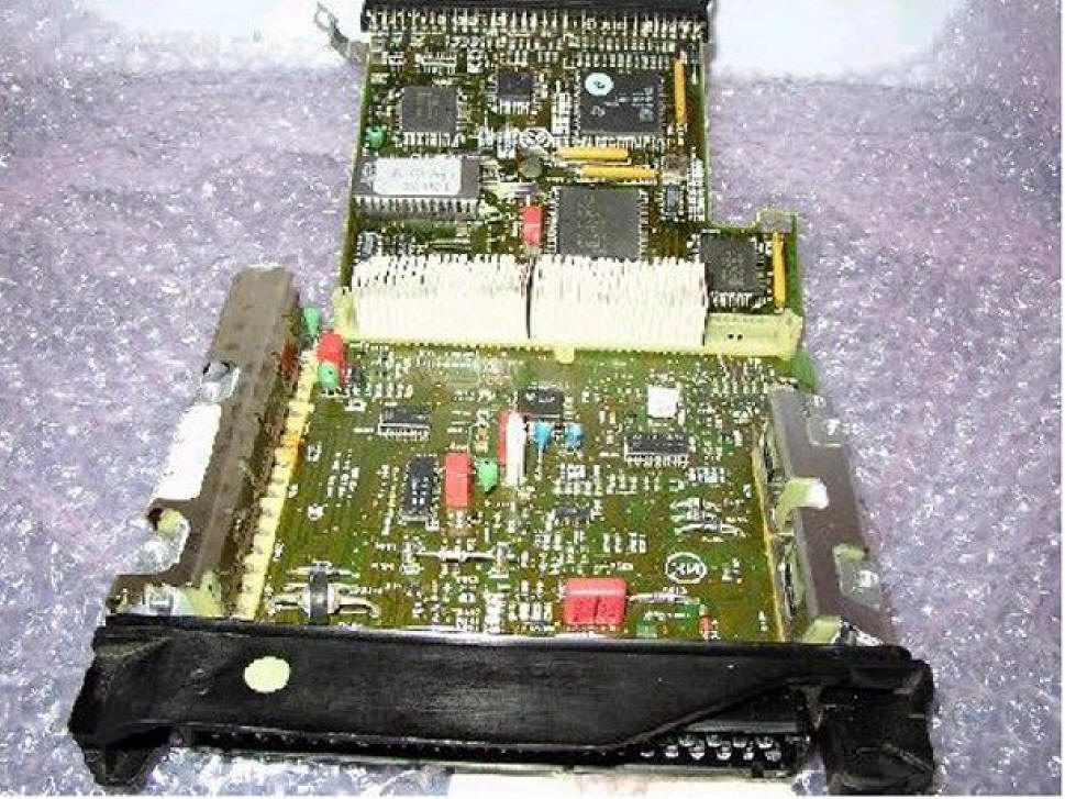
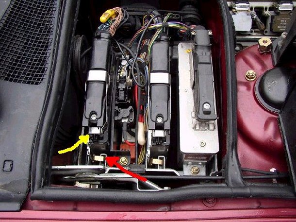
Here is where the DME lives on the V8, nearest to the windscreen. Before you
start I recommend that you disconnect the battery and leave it sitting with the
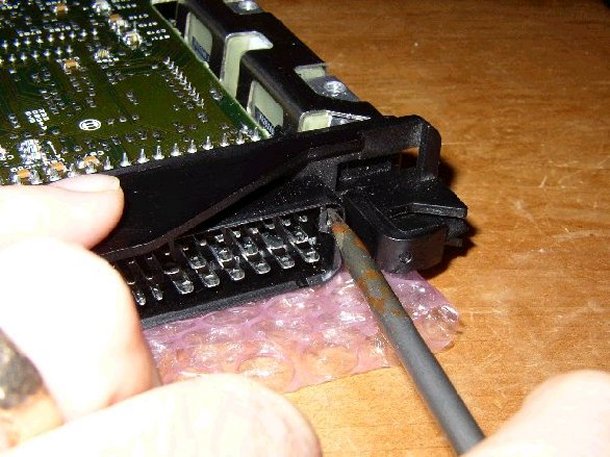
battery disconnected for 10 minutes. To remove the connector from the DME lift
the catch (YELLOW arrow), and pull the connector away from the front as shown
here. The connector hinges from the back, don't bend the wires too much but get
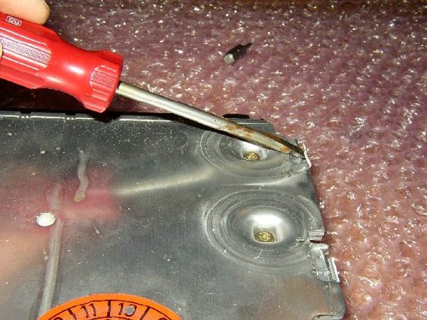
the connector out of the way of the metal clips. There are two metal clips (RED
arrow), these are just pulled up using the pliers, they are quite stiff so make
sure you don't mangle anything on the way out. The DME can then be pushed
towards the front of the car and then lifted out, mine was a bit constrained by
the electronics to the right in this picture but came out all the same....

With the DME safely out undo the upper screws with the Torx drive.....
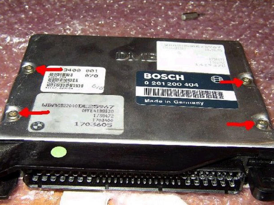
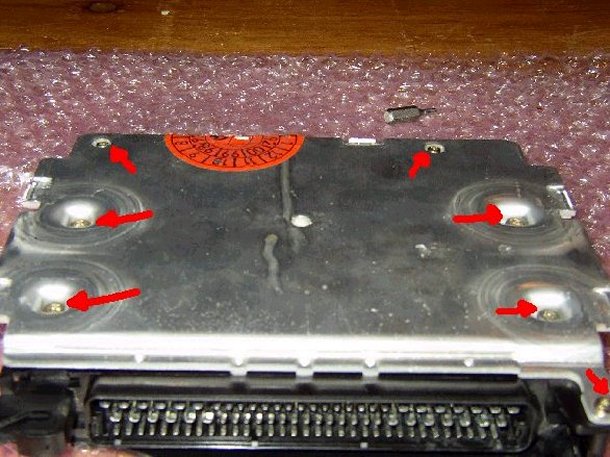
The lower half is held by four large Torx bolts and three small ones, undo them
all....
The case is held together by a few bent-metal clips, if this is the first time
the DME has come apart they will bend.....if this has been done before (and will
have been if the car was serviced at a main dealer and the software upgrades
have been done) then the metal clips will drop off....no great loss.....
Lift out the centre of the plastic pillar support, it will come all the way
out......
With the covers now removed undo the Torx bolt securing the PCB....
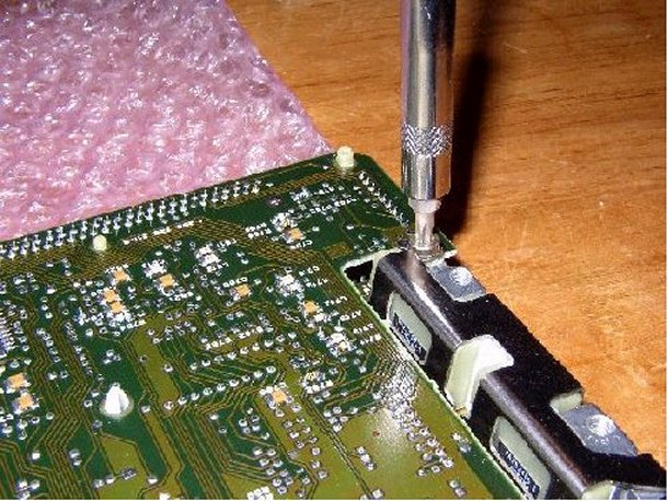
Then press together the PCB securing clip as shown here, slightly lift the PCB
so that the clip is left unsecured.....
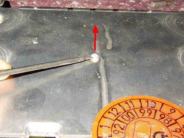
Next, lever apart the rear PCB pillars so that they are disconnected.....
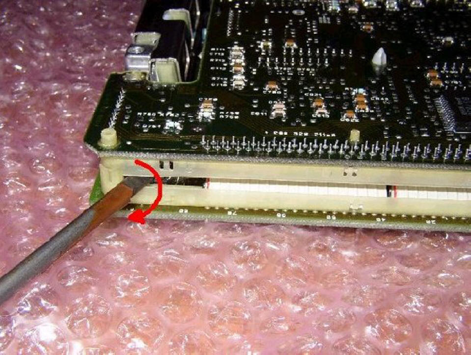
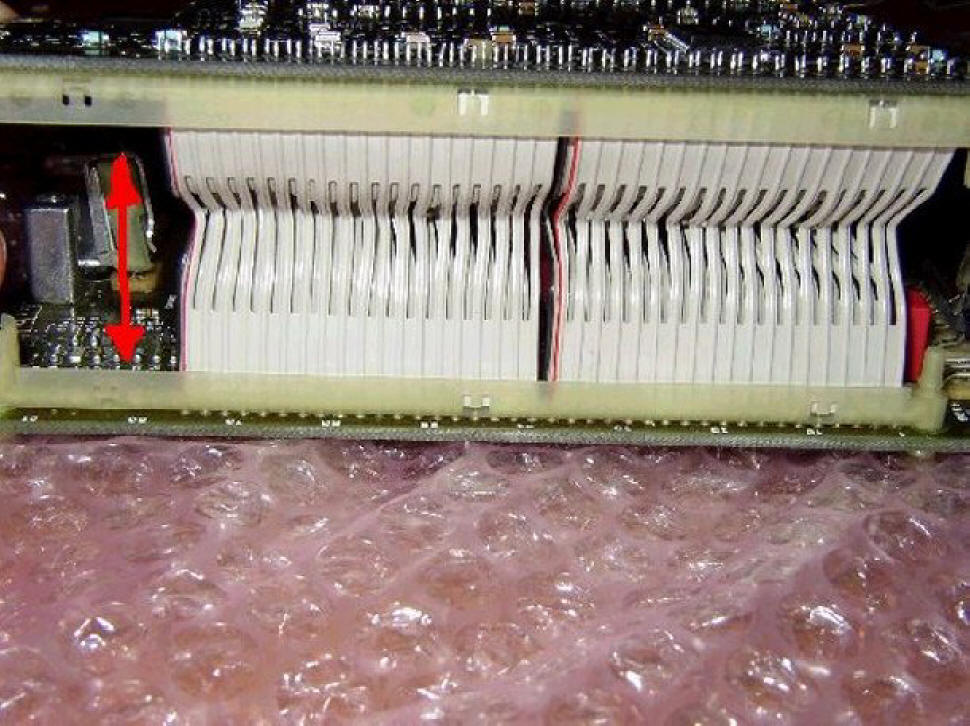
With the rear pillars disconnected and the PCB clip squashed lift the back of
the PCB and straighten out the wiring, it doesn't have to be completely straight
but similar to that shown here.....I failed to do this when I did mine and took
ages to work out that the wires needed to be straight before the PCB would come
out!....
Give the connector clip a quick tweak (mine only had one on one side but I
expect there to be one each side)....they should remain in the open position due
to the tilt of the PCB.....
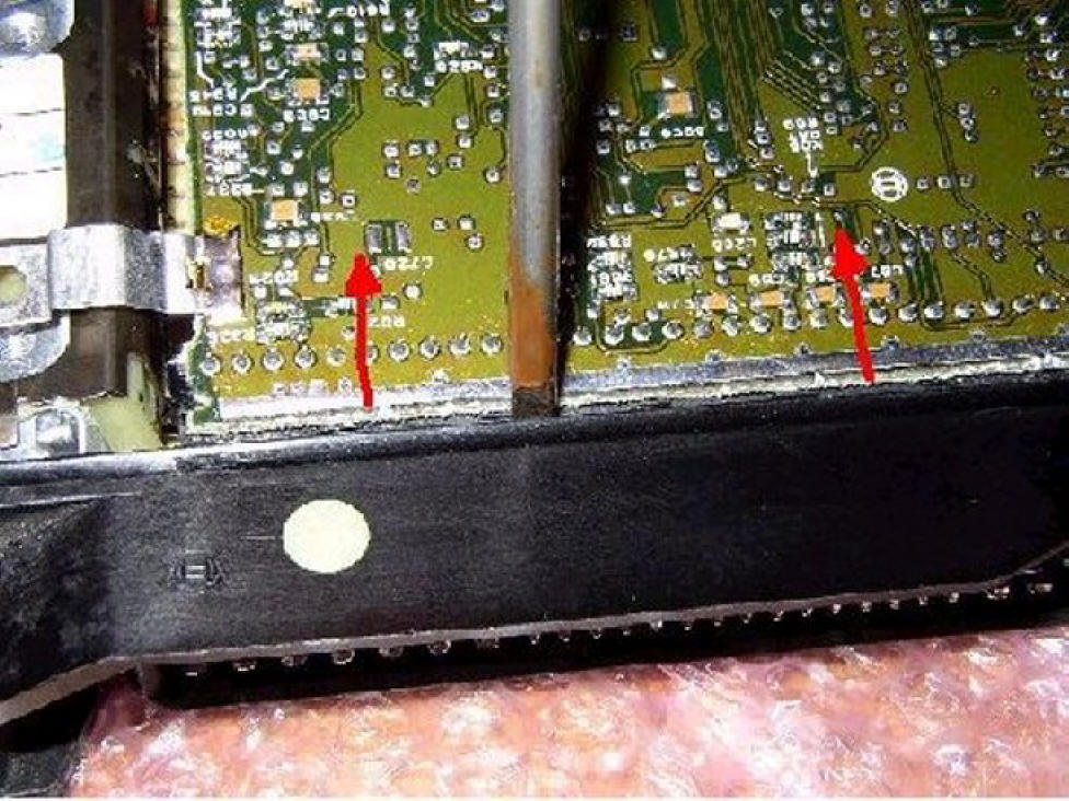
The PCB can now be moved backwards with a bit of a tweak, note that the top row
of connections are now almost touching the middle row, this is how it should
be......
Now the top PCB can be tilted backwards away from the connector, the top row of
connections are part of the top PCB!......
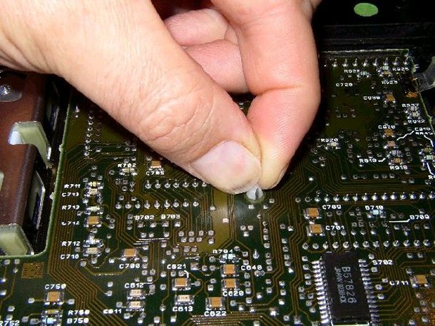
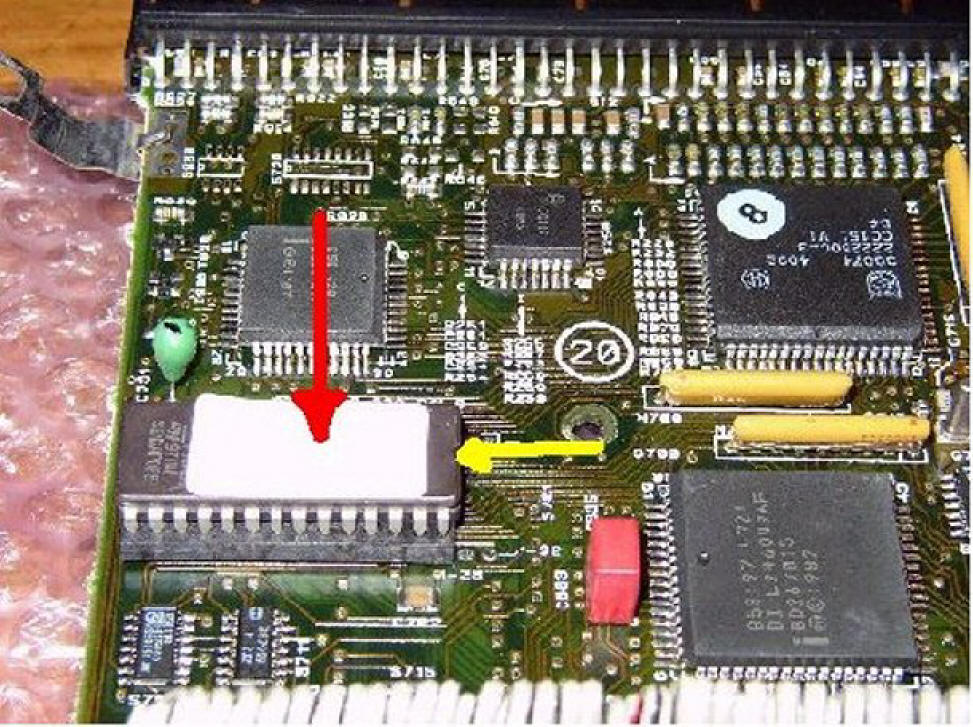
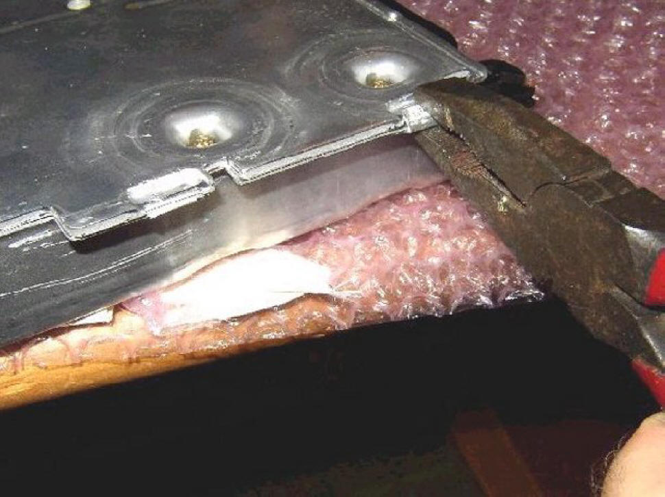
Here's the EEPROM that needs to be changed. I seem to have forgotten to take a
picture of the cover that was fitted to it. This plastic cover clips over the
EEPROM and helps to secure it in place. The plastic cover has two slots on the
long sides, you can fit a small flat-bladed screwdriver in them and give them a
quick tweak outwards to lift the lower edge away from the EEPROM carrier. I just
used my fingers to remove the cover, it is quite thin and flimsy but didn't fall
apart.....Note that the old and new EEPROM has an indentation at one end as
shown by the yellow arrow, make sure the new one goes in the same way around....
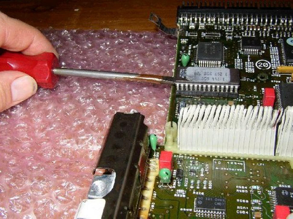
Lever out the old EEPROM using a small flat-bladed screwdriver, a little bit at
a time from each end. Wiggle the screwdriver under the EEPROM as you lift it up,
don't rush it and don't bend all the legs. The EEPROM should effectively be
lifted straight upwards, too much of an angle and the legs may be damaged....you
never know if you may need it again. Once the EEPROM is out stick it on the
anti-static foam that is supplied with the new EEPROM.....
Remove the new EEPROM from the anti-static foam and ensure that you touch the
DME with your other hand before fitting it in the socket, this will ensure that
you, the new EEPROM and the DME are all at the same potential. Carefully align
one of the long edges so that the EEPROM legs are all above the sockets and then
lower the other side towards the socket, as long as the EEPROM has been properly
prepared (and the Star Chip was) the legs should align perfectly. When all the
legs are above the socket and are correctly aligned carefully press the EEPROM
into its socket. Make sure that you only apply a little force, if too much
resistance is felt then one of the legs are not correctly aligned and will bend.
If this happens remove the EEPROM again using the previous instructions and
straighten the leg(s) using a plain edged pair of pliers, the legs will
withstand quite a few bendings, they are not brittle.Make sure you got the new
EEPROM the right way around (as shown in previous post) and then push the
plastic cover back on the EEPROM. You will have to slightly prise the cover to
get it over the EEPROM and its carrier.....
Right, time to stick it all back together.....Carefully bend the top PCB over
and slide the top PCB connections into the front connector.Poke the wires at the
back towards the centre of the unit, this will bring the upper PCB down.Ensure
that the front of the top PCB is within the connector and pushed forward, now
squash the PCB pillars together until they click.Ensure that the PCB securing
clip in the centre of the PCB has popped through the hole, push the PCB onto it
and ensure that the clip has opened and secured the top PCB.Refit the Torx bolt
that secures the top PCB in place......
Refit the Torx screws to the top and bottom covers. Squash the (remaining) metal
clips over the case.....
Refit the DME to the Ebox, ensure that the metal clips are correctly aligned
with the DME as you push them back into place using a pair of pliers, it is
possible to miss the edge of the DME. The clips serve to press the DME against
the chassis of the Ebox and are required to effectively heat-sink the DME...don't
miss the clips off!
The connector now needs to be refitted. This took me ages until I realised that
the connector has to be at quite an acute angle so that the rear securing tab
slides into the receptacle before the front of the connector can be lowered.
Don't apply excessive force, it should connect quite easily. Lower the metal
securing clip into place as shown in this picture.....
Fit the lid back on the Ebox (it needs the lid on for the air circulation to
work properly), reconnect the battery. Find out you've forgotten the radio
code....swear a bit and start up the engine.........
WHAT TO EXPECT
The new software will not know what it's up to to start with, the engine should
slowly regain its idle speed of around 500RPM with the A/C off or 600RPM with it
on. It may stall when you put the car into gear (mine did), but re-started OK
and didn't stall again. Drive the car in differing conditions (driving like a
granny, giving it a good thrash) and the DME will learn the best settings.
I whizzed up the A3 after a bit of back-lane driving and the car failed to shift out of 4th gear at 85MPH in 'E' mode. This only happened on my first blast and all worked correctly after going around a roundabout.Gear changes are now slightly delayed to where they were before, it makes the car a lot livelier, 'S' mode is very quick with changes being made right on the red line. Want to overtake someone when in 'E' mode?...don't bother sticking it in 'S' just stick the boot down for amazingly quick change down a few cogs and away you go.
MPG is
indicated to be about 3MPG better (now showing 30MPG for a A road- motorway trip
as opposed to 27MPG before, however, I don't believe it).I don't recommend doing
this without disconnecting the battery. The DME has an unswitched live feed, you
will only need to drop the connector on a metal surface for upsetting
fireworks.All in all worth doing.Just don't forget to have a note of the radio
code before you start.......
All done, time for a cup of tea......
P.S. If you need any help just contact me via the Forum......Timm....
P.P.S This is an extract from the post I made in the old E32 Forum. I've driven
about 40,000 miles since the chip was fitted and the MPG increase WAS real and I
still get around 31MPG for the round trip from Hampshire to Bristol and back
(32.4 on my last trip on Monday).......
![]()
