TIMM'S BMW E31 AND E32
REAR BRAKE AND
HANDBRAKE REPAIRS AND ADJUSTMENT
The following post details the problems
encountered while repairing the rear brakes and the simple things I found that
would have made the repair much quicker. The repair took around 3 hours, I
reckon I could do it in less than an hour now. I apologise to those who do this
on a regular basis as it should be a simple job but due to my incompetence, it
took a lot longer!!
Right, first, road wheel off (all pictures are for the rear offside on a '93 V8
730i). MOST IMPORTANT: You MUST use an axle stand under the car next to the
jacking point. The amount of force required to undo the fixings on this job is
sufficient to roll the car off the jack. DO NOT attempt to do this job without
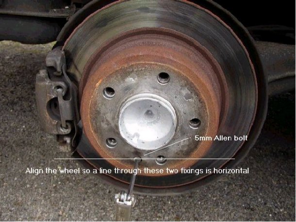
the axle stand!The disk/drum rotor is attached to the hub with a 5mm Allen bolt
as shown here. Align the hub so that a line between the two fixings is
horizontal....
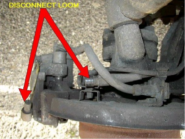
Now disconnect the brake wear sensor. This is a two-part rubber connector, it is
not difficult to separate but be careful not to damage the thin and weedy wires
that go to the sensor. After the connector is separated fit the car half of the
connector back in its clip.
Now it is time to remove the two 17mm bolts that hold the calliper assembly to
the hub assembly. They are very tight and I tried a number of methods to remove
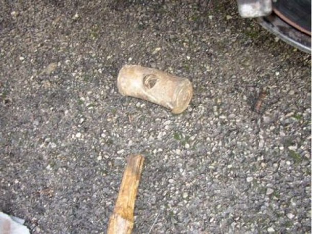
them, a two-foot extension on the socket would not do it. A bit of a whack
seemed in order but we all know not to hit metal tools with a metal hammer so I
used a hide mallet instead.....well for a while anyway.....
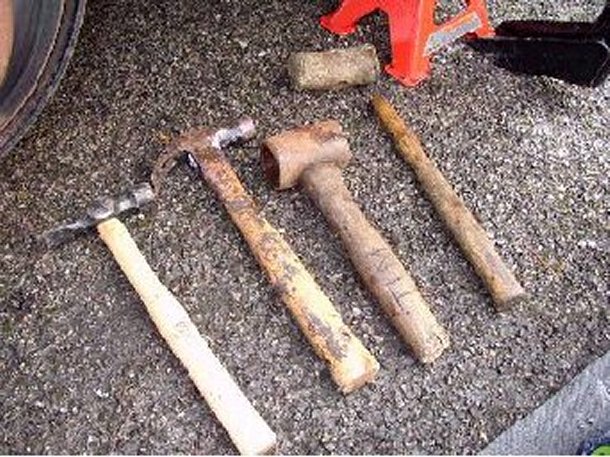
Both bolts eventually came off using the lump hammer from this selection. Make
sure you use an extension on the socket for the upper bolt as it is easy to
clout the speed sensor....
Once the calliper is free hang it out of the way. Do not let it dangle on the
brake hose as it is quite heavy. An old fashioned metal coat hanger is best to
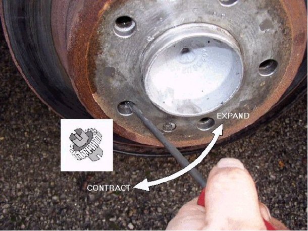
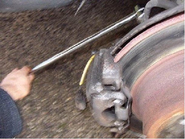
use, I secured the top end to the coil spring.The disk/drum rotor can now be
pulled off. However, if the brake is binding it will not come off so easily. It
is also possible that the shoes have worn a groove into the drum and this will
prevent the rotor from being removed. The get around this problem the shoes can
be contracted using the adjuster at the bottom of the shoes. As long as the hub
is aligned as shown previously the adjuster can be rotated using a long,
flat-bladed screwdriver. It takes a couple of goes to get it right but persevere
by adjusting it the direction shown until the end of travel is reached.....
With the disk/drum rotor off remove the shoes by rotating these devices by 90
degrees. I struggled trying to get them back on later with a pair of mole-grips
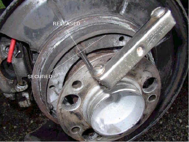
until I realised that they have a 5mm Allen-key fixing in the centre! They are
also scribed with a mark to show their position, the marks and their meaning are
shown in the next picture.....
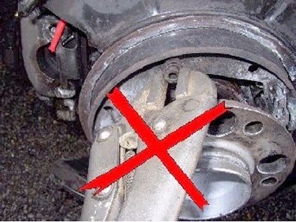
The right way......
After those two fixings are removed disconnect the upper spring and the shoes
can be removed by expanding them over the hub. As long as the lower spring is
still in place, the adjuster will stay connected to the shoes. Use brake cleaner
to remove all the dust and muck from the rotor and the hub assembly.....
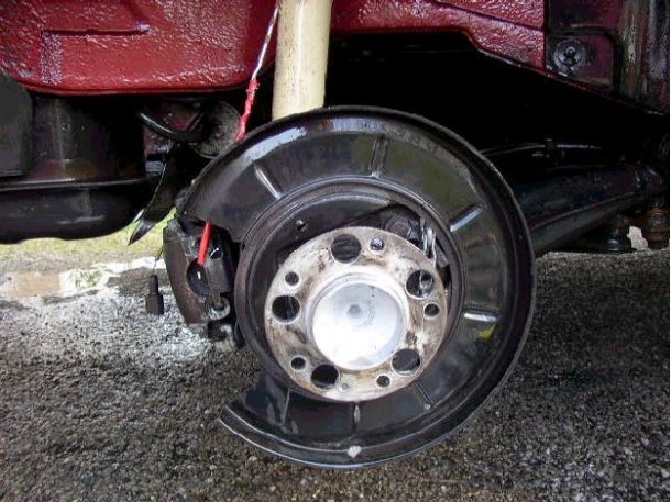
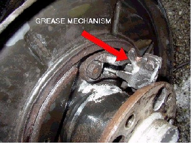
The handbrake mechanism was quite stiff even though this silver stuff had been
spayed everywhere. I removed all the gunk from it and greased it until it worked
smoothly.....
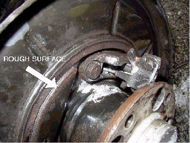
The surface where the shoes fit was rough and pitted, this won't help the
operation of the shoes so I used some wet and dry to smooth the surface and then
put a light coat of grease over the surface (but not enough to get on the
shoes).....
With everything clean and greased, I put the shoes back on (dead easy with an
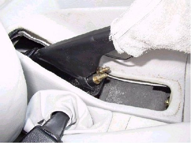
Allen key to do up those spring fixings!). With the handbrake released, the top
of the shoes should rest on the backplate casting and should not be expanded by
the expander assembly. If the shoes are not resting on the casting remove the
soft cover on the handbrake lever (it pulls out from the top) and adjust the
cable until they do. Ensure that the shoes operate smoothly and always return to
the casting. If they fail to do this they are going to bind at a later date,
replacement of the cable will be required if they fail to return.....
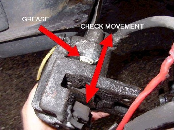
Next I had a look at the calliper. This assembly should slide quite freely on
the shafts shown here. Mine was OK but I greased the shafts anyway. When moving
the slide mechanism the pads pull out of the piston (they are held in place with
an expanding clip) so when the shafts have been greased and the slide moved back
into the correct position pop the pad back in place. Carefully check that the
piston moves by applying hand pressure on it. It should move slowly with little
pressure. Do not push it far or the brake fluid will be forced out of the
reservoir....
Refit the disk/drum rotor over the shoes, with the adjuster fully contracted it
should fit easily, if it does not, something is not right. Refit the calliper
assembly, the pads may need pushing apart slightly but not far. Tighten up the
bolts using a torque wrench to that specified (22-ft-lb)......
Check that the brake-sensor connector is clean and free from moisture and
reconnect, fit this back in it's clip. If the connector was dirty or wet inside
clean it with a brush and WD40 before assembly.With the handbrake released,
ensure that the rotor is free to rotate and then adjust the expander as shown
earlier until the brake just bites and then release a couple of clicks. Pull the
brake-lever up by a couple of clicks and adjust the cable until the rotor starts
to bind. Release the lever and ensure that the rotor is free to move. Refit the
handbrake cover. Refit the road wheel.
That's it, all done, time for a cup of tea.......

P.S. If you are working on the nearside rear brake then all positions are
reversed and the alignment method for the adjuster is not valid (I think),
alignment of the hole over the adjuster is reversed....
![]()
