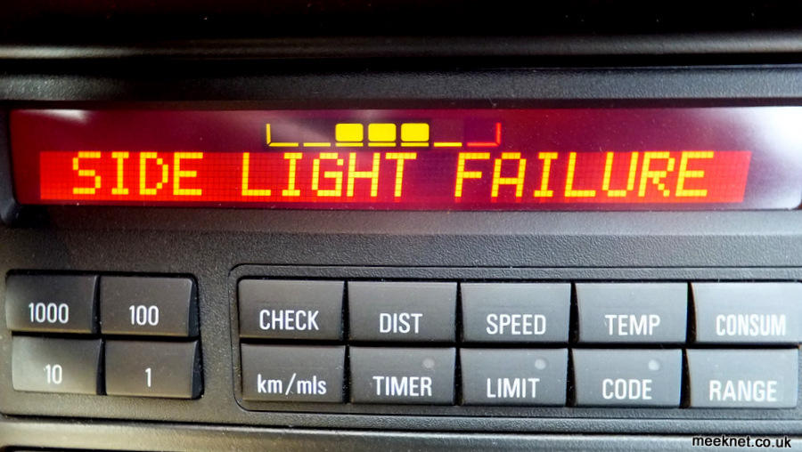
Well, it was pretty impressive, that
is, until the ignition was switched ON and I got the obvious:
I experimented first with an 0805 case size but found it a little too fiddly - but it did work.
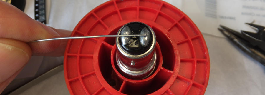
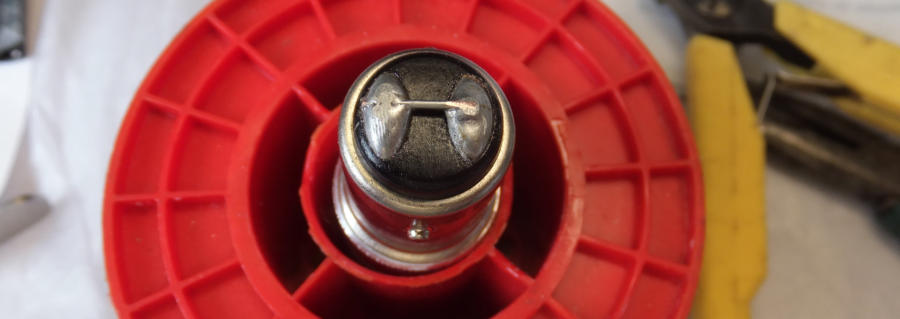
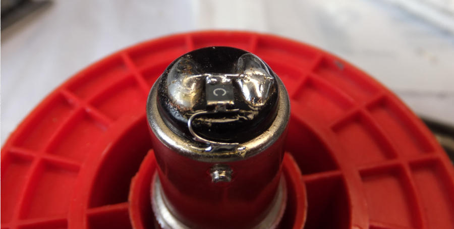
Below, here is how to fit the device above, a 1210 PTC. Start by joining the
two contact together with tinned-copper wire
The reason for the link is to increase the brightness - but more importantly - increase the current demand so that the bulb will pass the hot
bulb test. Although soldering the two contacts together has been done for years on the E31 to increase the brightness on the standard tungsten
bulb, it can have an unfortunate side effect on cars that have Daylight Running Lights (DLR) as they alone use the 21W element - on these
models soldering the two contacts will make the car carry on running when the ignition key is removed! Very few world models use the
DLR’s, but if your car is one of them don’t solder the contacts together (Canada is one of the few)!
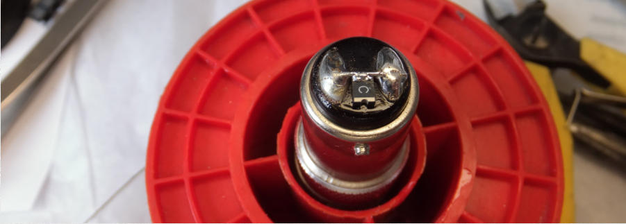
Next, fit the PTC device:
I tested this on the E31 and all is well
Timm's BMW E31
Solving Side Light Failure Messages when using LED's in the FTP's
Updated to include other using LED’s in other lights and an Ebay LED (brighter)
The E31 could pass itself off as a car designed in the 21st Century - except for the dim, yellow sidelights. We know how to get the
brightness up by soldering the two terminals together as described here. But recently, the yellow colour is really looking old. So, I installed
a superbrightleds.com 1157-W45-T bulb into the FTP and it looked like this:
Which is a bit disappointing, but not entirely unexpected. I can't put up with error messages, nor do I want a huge resistor
strapped to the chassis and poorly wired into the FTP loom. There must be another way - and there is!
Let's look at why we get error messages in the first place. The system is designed to find incandescent bulbs (standard tungsten
filaments) that have failed. It does this in two ways:
It measures the current demanded by the bulb when it is operation (hot bulb test)
It measures the voltage across the bulb when the light is NOT on (cold bulb test)
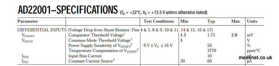
These two tests are done by a bulb-checking IC within the LKM, as far as I know, this is the same IC that is used in the E32
LKM, the AD22001. The important bits about this IC are shown below:
The simplified explanation of what the LKM IC expects from the bulb:
When the bulb is OFF, it expects the bulb to have an electrical resistance below a certain
level
When the bulb is ON, it expects it to demand a current above a certain level
The standard 5W tungsten bulb has a cold resistance of a few Ohms (when it is not operating), and demands
around 400mA when it is operating. So, those are the two factors that have to be mimicked if you want an LED
bulb to operate without Bulb Failure warnings.
What does the LKM measure when an LED bulb is fitted?
When the LED bulb is OFF, it will measure an almost infinite resistance (and fail the cold
test)
When the LED bulb is ON, the current demand is usually quite small (and fail the hot bulb
test)
The cold test is done at a low voltage - LED bulbs will show a very high resistance. As LED's are much more
efficient than Tungsten bulbs they demand a lot less current.
There are a couple of usual ways of getting around this problem:
Stick a resistor across the supply to the bulb - but this will need to be large enough to dissipate the heat
Stick a capacitor across the supply to the bulb - this is seen as a low resistance during the cold test
Both of these methods require fiddling with the loom to the FTP's - and are an ugly solution. The resistor will get
hot, so needs to be fixed to the chassis, or large enough to dissipate the heat without heat-sinking. The capacitor
will fool the LKM during the cold test, but the low demand of the LED bulb may not allow the bulb to pass the hot
test.
What we need is an LED bulb that demands sufficient current to pass the hot test, but also has a low resistance at
low voltages to pass the cold test. Some new LED bulbs are coming on to the market that have resistors fitted, but
these have the downside that they produce very little illumination and get pretty hot (due the heat dissipated by
the resistor). I have one here - and it is pretty poor.
What we need is a resistor of a few Ohms that turns itself OFF (becomes high resistance) when the LED
bulb is switched ON. That would solve both problems, it will pass the cold test, but will not dissipate a lot of heat
when the bulb is operating. Fortunately, there are resistors that can do this, they are called PTC resistors,
these are usually used as fuses for sensitive electronics (the PTC stands for Positive Temperature Coefficient).
These devices have a low resistance (a few Ohms or so) until a current is passed through them that is above their
'trip' point, they then go high-resistance. When the current is removed, they rapidly return to a low-resistance
state.
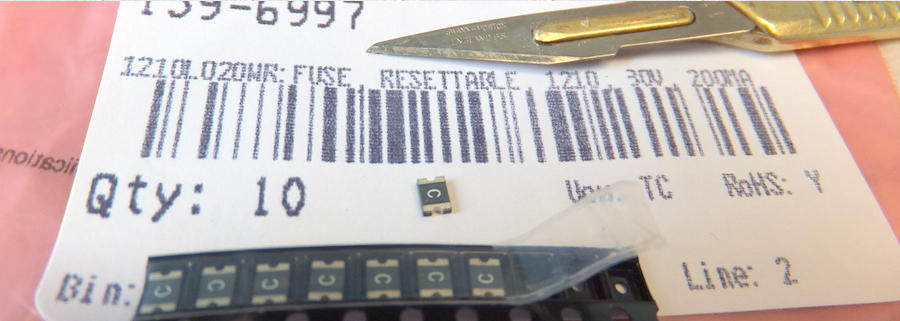
PTC resistors used to be massive lumps, often used to energise the de-gaussing coil on CRT TV's. These days they
can be tiny, the smallest in general production is in 0403 case style which is 0.04" x 0.03" or 1mm x 0.75mm. The
best size to use, which is a compromise between small size and ease of soldering, is a 1210 case size as shown
below, this is the actual size I ended up using:

Can this trick be used on any other lights on the E31?
I’ve been slowly working through the lighting on the E31 to see what works and what doesn’t - here’s a simple list:
•
Brake lights: Using LED lights stops the cruise control working on the V8’s. The CC actuator’s clutch’s 0V connection is routed
through the brake light bulbs, It does this as a safety feature, when the lights illuminate the clutch is robbed of its 0V and dis-
engages. The LED lights cannot provide enough current to keep the clutch engaged.
•
Indicators: If 400mA LED bulbs are used along with a PTC you can replace ONE light on each side out of the three. I’ve used an
LED bulb in the rear indicator on each side. No error messages. Try replacing TWO bulbs (FTP and rears) and you will get a fast-
flash error. Some LED’s are too long, they fit in the rear cluster but not in the FTP’s
•
Rear Side lights (also used as parking lights): Using a 300mA - 400mA LED bulb makes the side lights much too bright, it
looks like you have left the rear fog lights on - not a good look. I’ve kept the tungsten lights, they look better.
•
Rear Fog lights: Using a PTC device will stop errors on 400mA LED units, but, Tungsten lights give a better light spectrum. The
LED units tend to show as being white rather than red and are less effective. I’ve kept the Tungsten bulbs.
•
Licence-Plate lights: I added a piggy-back resistor with its own heatsink to some LED licence-plate units and that worked fine
but was a real pain to fit. Mike in CT came up with a much better idea, solder a standard Tungsten festoon to an LED unit (one
without a heatsink) - and that works very well. I’ve had a pair on for six-months and they have caused no problems at all - and
so much easier to construct and fit
•
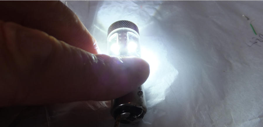
Reversing lights: Easy, use a 400mA LED (pictures below) without any modifications, these are not checked by the LKM. Use
one with a lens at the end and they will make a huge difference. Some LED units are too long and will not fit.
•
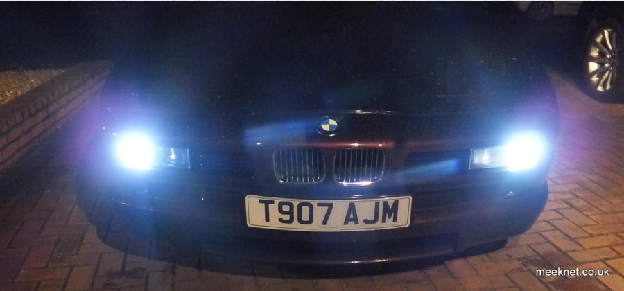
Headlights and front Fog lights: These are getting better that the original weedy units, but they are not good enough yet. More
information on the limitation of these bulbs can be found here
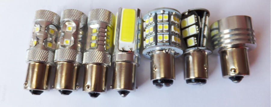
LED units I have tested are shown above. From the left, two 400mA units, fitted to rear indicators. Next, advertised as 800mA, this is
actually 400mA and doesn’t fit anywhere. The next one is brighter and demands 450mA or so but doesn’t fit anywhere as it is too
long. The multi-LED unit is used in my FTP’s. The last two are hopeless, dull and demand around 100mA - a complete waste of time.
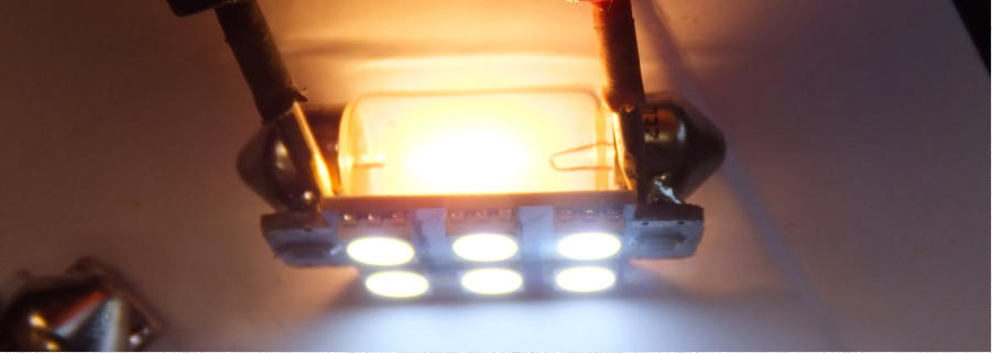
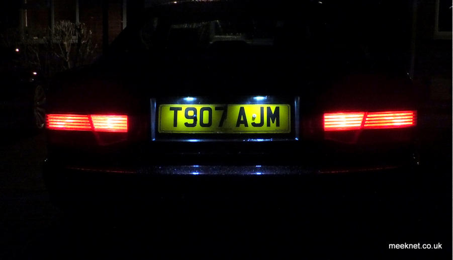
Above is a cheap licence-plate LED unit soldered to a standard 5W 38mm festoon bulb and then fitted to my E31 below:
Use a file to provide a suitable are for the solder on the edge of the bulb
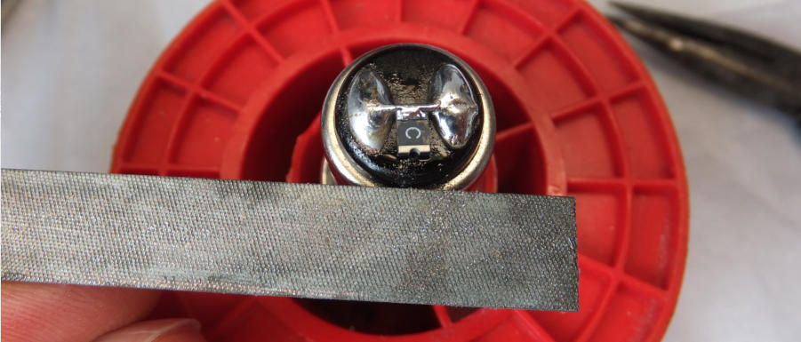
Tin the bulb first, it makes it much easier to connect the small wire - the wire I am using is Kynar, but any
thin-gauge tinned copper wire will do just as well.
A quick test on a 12V supply and all good. This bulb came from Ebay instead of SuperBright - it was claimed
to be something ridiculous like 80W, but on test it demanded 700mA when cold and then slowly reduced the
current demand to 450mA after a few minutes as it heated up. So, something like 7W or so.
The length of the bulb was the absolute maximum that would fit at 55mm - any longer and you have no
chance of fitting it. The bulb was also lensed at the end and that projects a lot of light forward rather than
chucking the light all over the place.
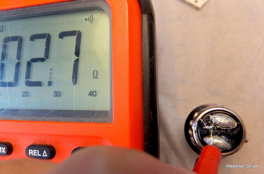
A check with a meter on Ohms shows that the PTC is doing it’s job (smaller PTC shown below) - the cold
resistance is well under the threshold of a few Ohms - the 1210 PTC is even lower with cold resistance of 2
Ohms or so.